

If you wish to remain anonymous, simply enter "anonymous" for your name and/or email. This is done mainly to prevent spam and other abuse. The owner of this site generally does not answer questions in comments.Īll comments are subject to approval before they are displayed here, so your comment will not appear immediately. All technical questions should be posted to the forum. Important: If you post a technical question here, there is no guarantee it will be answered. The forum provides a more robust environment for discussion. However if you would like to ask a question it is suggested that you use the forum instead. Comments can be things like suggestions, successes or failures, improvements, similar circuits, error reports, an answer to a previous commenter's question, or anything in between. If you would like to leave a comment, you can do so using the form below. The last 10 comments are currently shown. Water level low>water valve opened (heating system) But when I go to search for a time delay relay to build one, your site comes up second on Google. Last some days I was searching the same, which I want to used.Īaron, I have know you through the RX-7 world for years. How do I calculate the change required to the capacitor? i want to know more about delay. I'm looking to adjust the time of the delay for 1week. But I do want all the power I can get, to make sure the charge ignites. If I use 9V as my input power supply, do I have to change anything else? And, I am not going out to a relay, I am going directly to an E-Match, to trigger an ejection charge in a model rocket. I already get the cicuit in 12 volt,but my problem is i would like to increase my voltage into 24v so also increases my relay into 224v but wont work or oerate,pls help what to add components or change?i want 24v dc to run my motor I want to supply it 24v and my relay is 24v but i wont operate Thank you so much for taking the time to post it. This was EXACTLY what I needed to complete my project. I need someone to make me a very small circuit that is on for 10seconds and off for 60 seconds and then it repeats over and over using a 3v cell battery can the power supply can be reduced to 9v while using a relay of 5v. If I want to use a 5v relay which parts of the circuit is to be changed.
Simple delay timer transistor circuit mod#
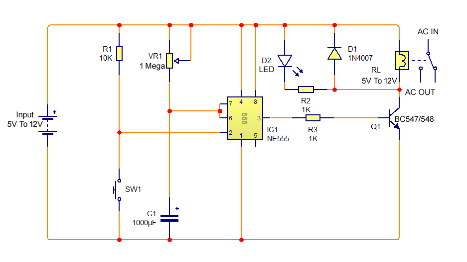
Thanks Aaron for the original circuit and thanks to WillyAG for the little mod needed for my purposes. This ckt used in agriculture purpose, out the water from water tank only for 60 sec. S1 can be replaced by a NPN transistor so that the circuit may be triggered by a computer, other circuit, etc.Īir Flow Detector, Wire Loop Alarm, Simple Two Speed Contactor DC Motor Controller, 7 Segment LED Counter, Simple Lie Detector, Low Voltage Alarm, Video Stabilizer/MacroVision Removal, Pulse Width Modulation DC Motor Control, Simple Polarity Tester, Pine Racecar Victory Judge, Rain Detector, Time Delay Relay, Time Delay Relay II, Stepper Motor Controller, Touch Switch, Video Activated Relay, Digital Keypad Combination Lock, AC Motor Speed Controller, Simple Servo Controller, Water Detector With Sump/Bilge Pump Controller, Simple Touch Switch S1 is used to activate the timing cycle.

You can use a different capacitor for C1 to change the maximum on time.The current capacity of the circuit is only limited by what kind of relay you decide to use. The time is adjustable from 0 to about 20 seconds with the parts specified. This time delay relay is made up of a simple adjustable timer circuit which controls the actual relay. A time delay relay is a relay that stays on for a certain amount of time once activated.


 0 kommentar(er)
